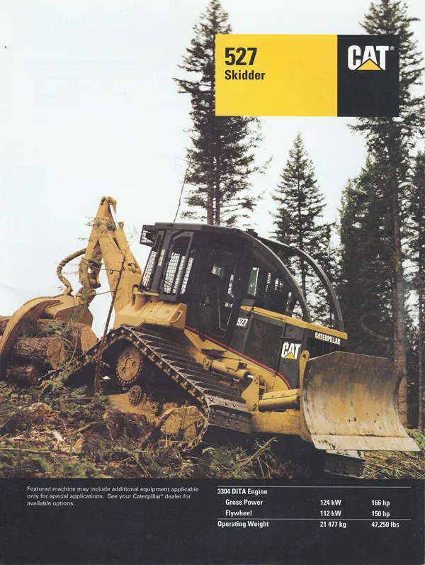
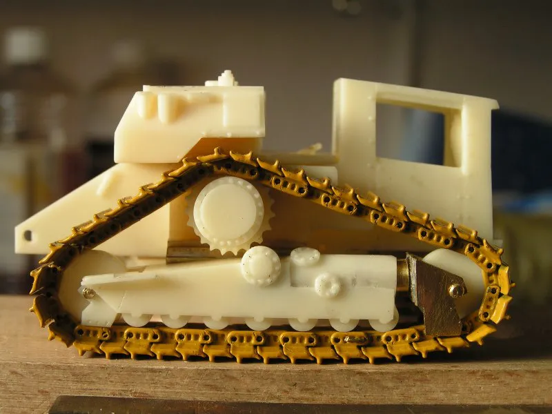
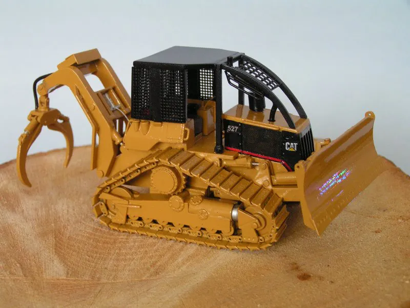
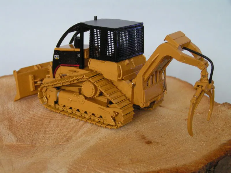
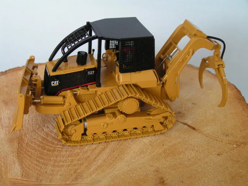
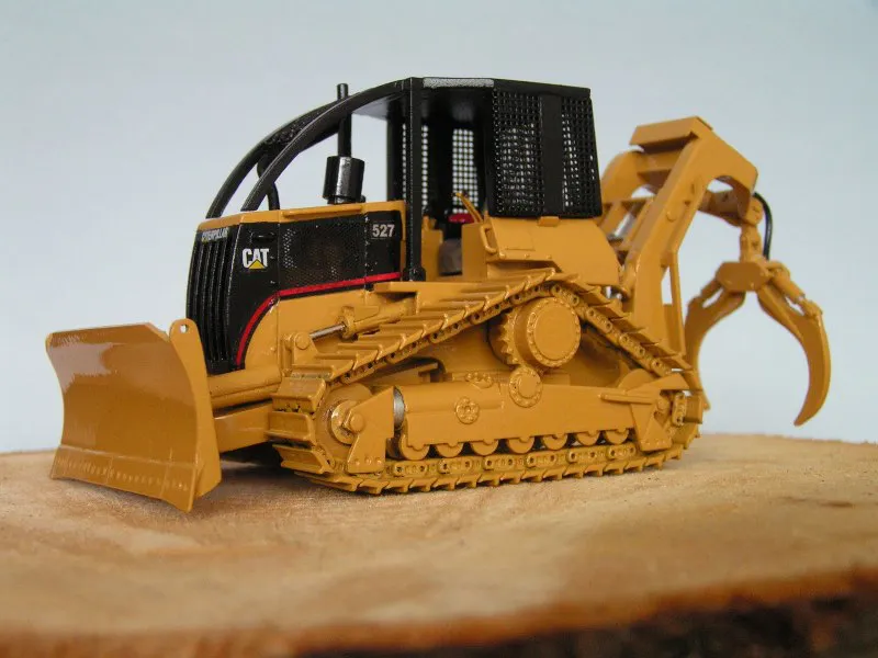
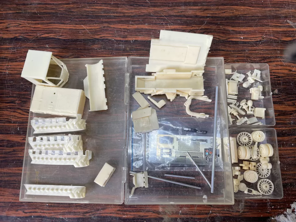
Custom scale model builder Ad Gevers shows you one of his latest projects: Building a Caterpillar 527 Tracked Skidder by using the resin Kit from CYPmodels in 1:50th scale.
In this "making of ...." you will see how this custom model will be achieved. Ad Gevers, will share his building skills through its construction photos with little notes and step by step it shows the making of a unique model of the Caterpillar 527 Tracked Skidder.
Enjoy reading & watching!
Ad and Wouter
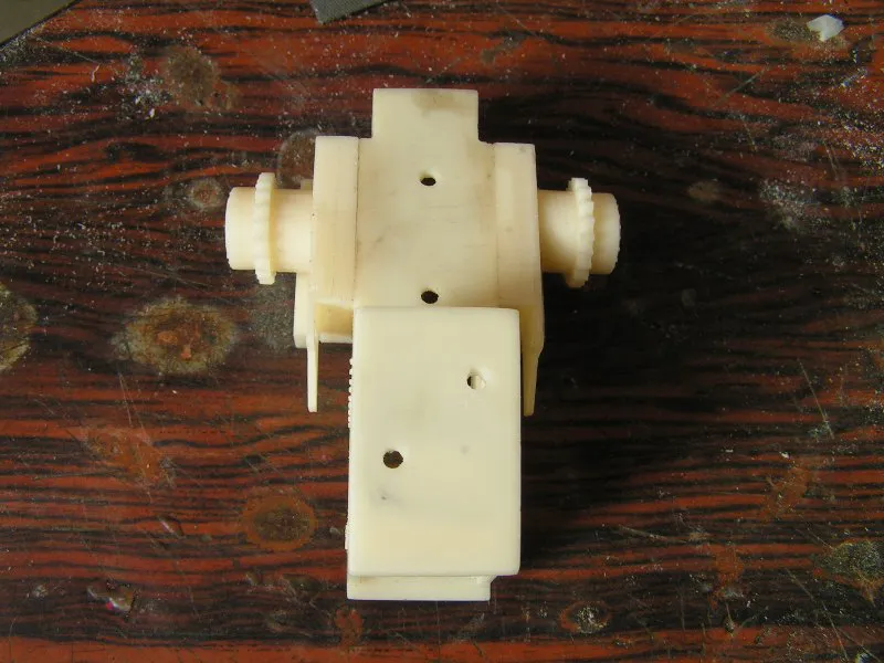
The frame
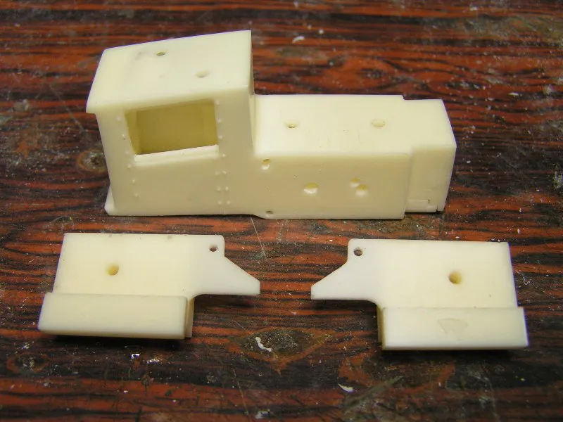
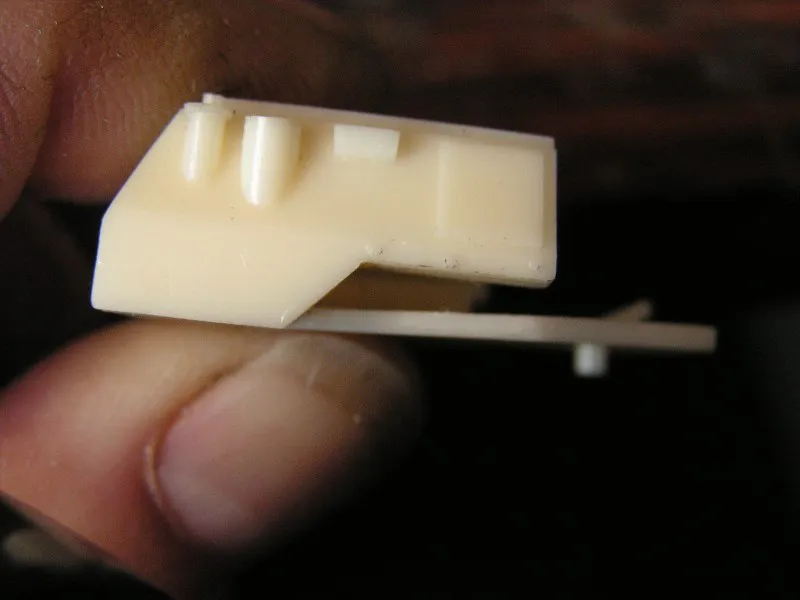
When building any kit it is important to take care that all parts thoroughly cleaned.Make sure all parts are present and try beforehand whether the fit is good.I decided on this Caterpillar 527 Tracked Skidder to use the metal tracks of the D6T Caterpillar Track-Type Tractor from Norscot go put in place of the one-piece molded static Tracks that are supplied with the kit.
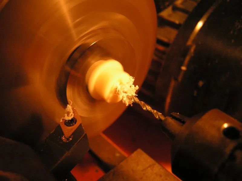
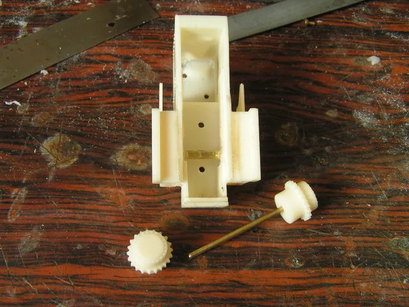
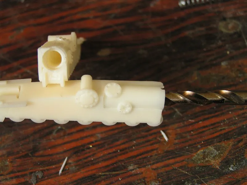
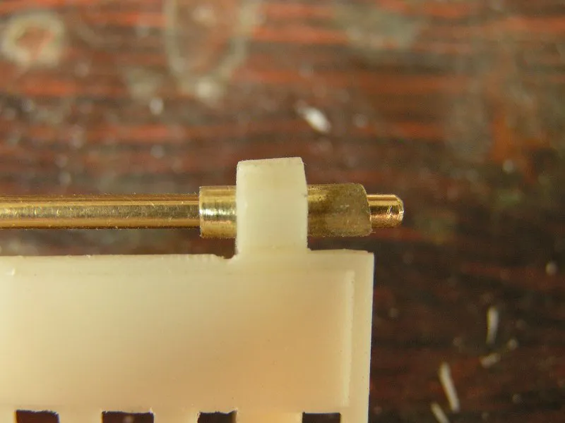
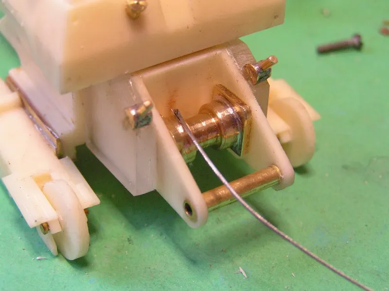
Because I already pre and separate drilled the hole in the sprocket shaft in both side pieces before they were glued, it turned out that when inserting the shaft, this ± 1.5 mm diagonally placed.
To fix this, I fixed two rollers on the turning lathe and drilled the hole so that they are well in the center and line come together to sit straight.
To fix the resulting difference in the holes, I have the oversized holes filed and with a larger sized tube filled. The axle then slid in the shaft of my tube and everything is placed right now.
Job done!
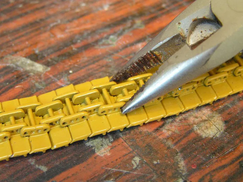
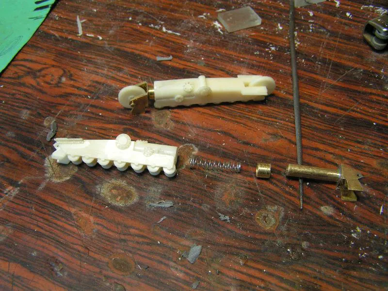
The Tracks
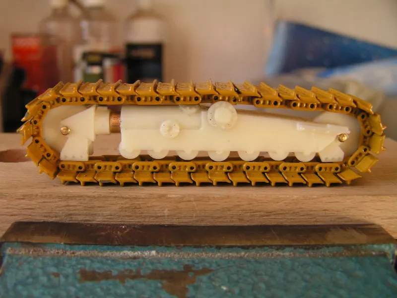
Before we can use the metal tracks of the Caterpillar D6T Crawler Dozer from Norscot instead of the of the one-piece molded static tracks coming with the kit a number of adjustments should be made to the tracks and undercarriage.
Before the metal tracks can be used, I first squeezed every link with pliers. This prevent them later during assembly yet again come apart from each other.
In the closing link I drill a hole. With a small pin I later put the total track together again and then it can be assembled in to place without any problems.
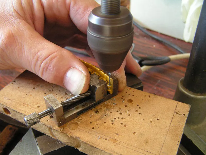
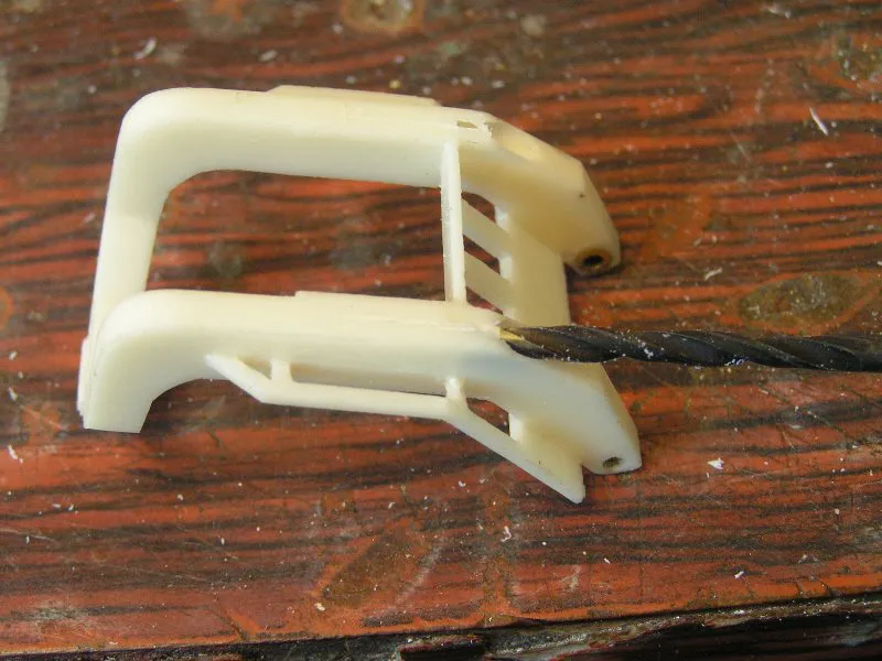
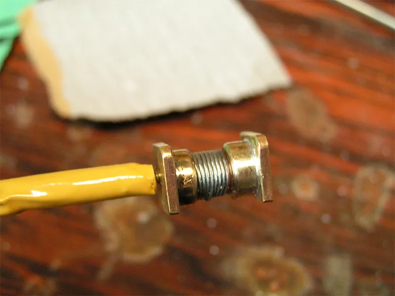
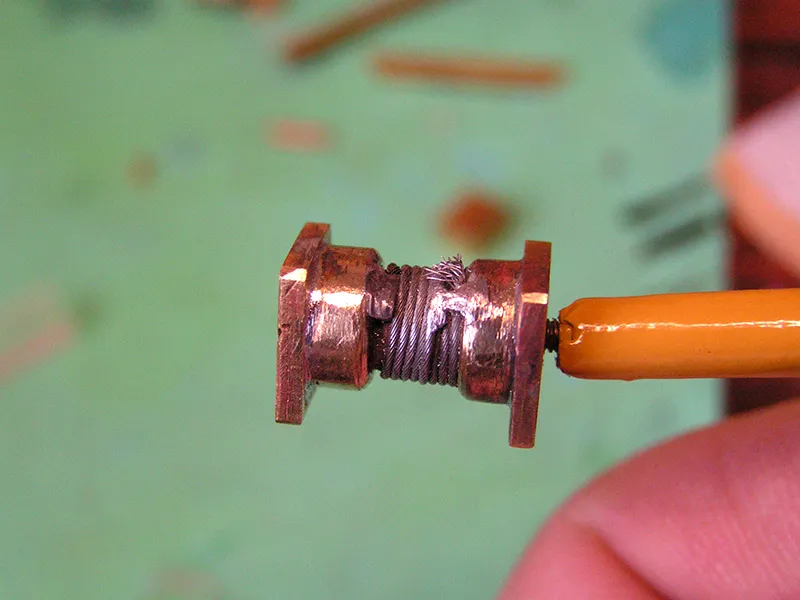
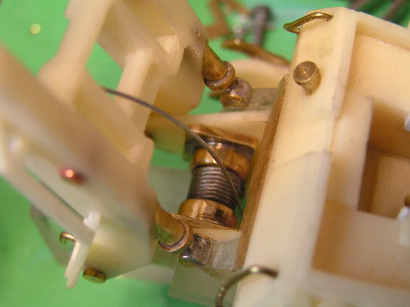
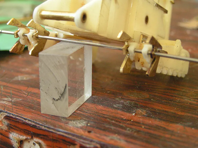
To create enough tension to the tracks, that eventually gives a tight drive on the machine, there has to be placed a spring in the undercarriage. In order to be able to place this spring there must be a hole drilled in the track roller frame so that the front wheel can slide in and out.
To determine the center of the tube where the spring (spring track release) comes in, I drilled a hole in a very thin round disc that fits perfectly into the undercarriage.
I can now exactly fix the center point tap, and then drill out to the desired outer diameter so that the spring can be placed.
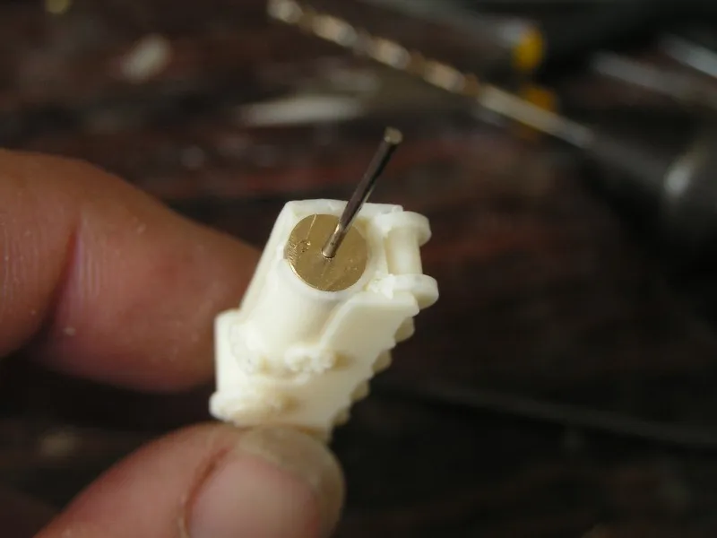
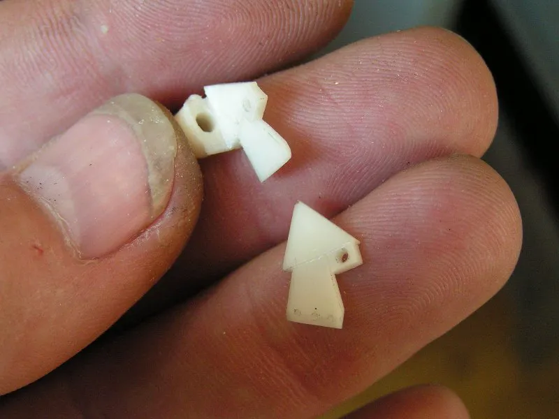
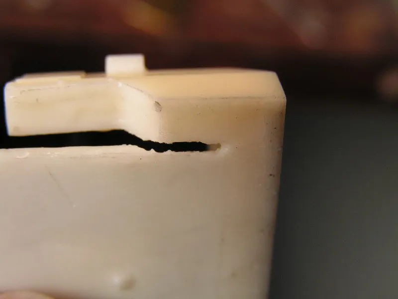
During the “try and fit” test to see how the result looks it became clear that the front idlers did not fitted the chains so that the rollers on the front of the machine not hit the chain.
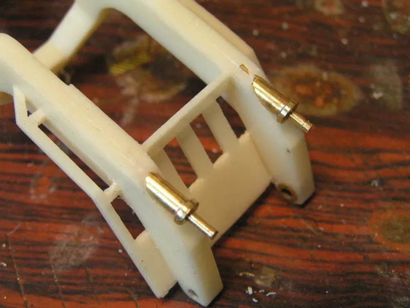
To make things worse, happened what I all along feared: The vulnerable resin wheel fastening broke off!!
This choice was no longer difficult: Now I had to make a new implementation of brass, and so therefore in the same job immediately the perfect solution could be made. A blessing in disguise!
Two hours of hard work later: A custom brass wheel fastening.
In the meanwhile, I also decided that I’m also go change the led- front and rear plates, but that's for the next construction report.
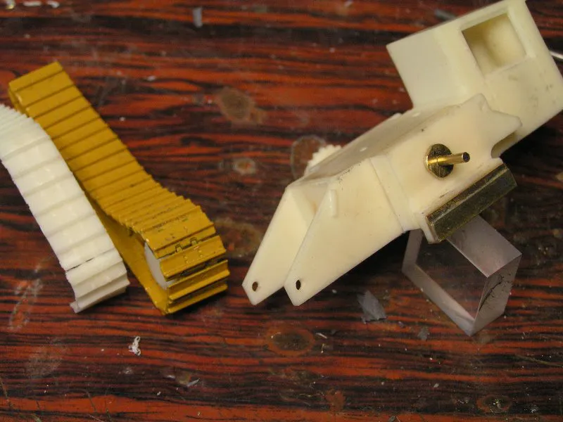
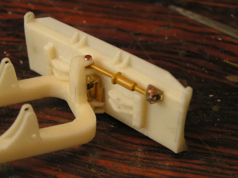
Finall Drive and Undercarriage
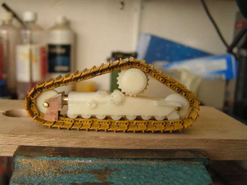
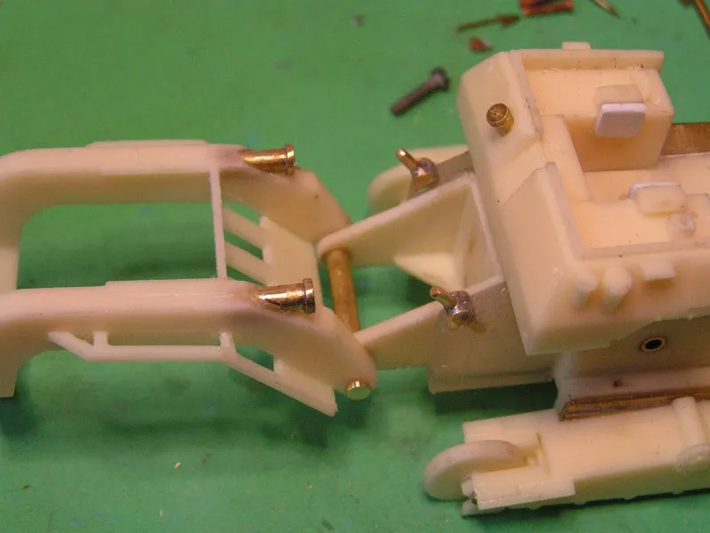
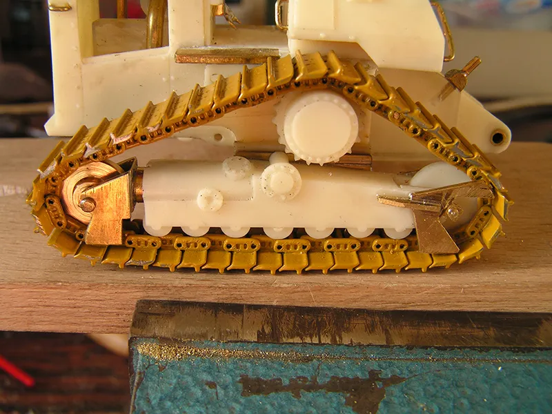
First a photo of all the extra and custom made components and the adjustments which have been made on the original drive from the kit. Now you can see what it is necessary to achieve that the new metal tracks be tensioned so that eventually you get a tight looking drive on the machine.
Because the metal tracks of the Caterpillar D6T are slightly wider than the supplied molded tracks of the kit, the sprockets and undercarriage should be also a slightly further (1 mm) more outside and therefore extra spacers and plates are installed on the frame.
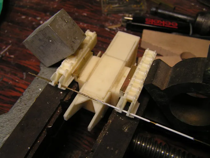
It was a considerable challenge to glue both undercarriages at right angles to the original frame. Using the bench vice and the necessary support tools, the whole was adequately fixed.
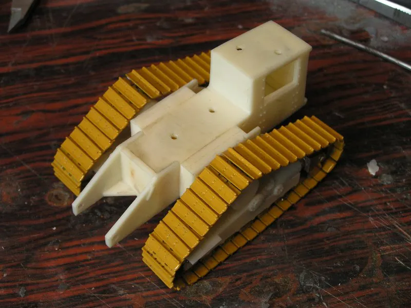
After all the adjustments the test run with the applied metal tracks from the Caterpillar D6T: A tight end result.
Adjustment of the Fuel tank and the Bottom plate
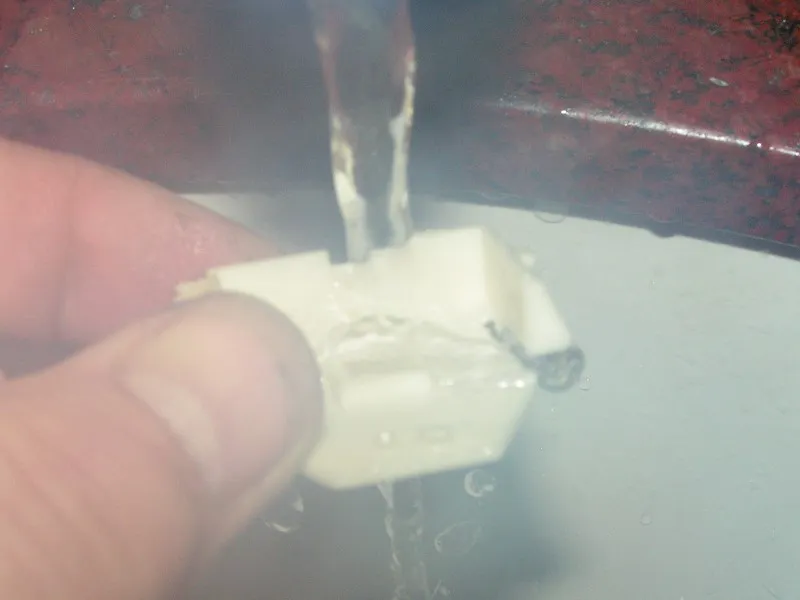
The challenges continue to arise. The bottom plate is unfortunately not straight casted with the fueltank section.What to do now?
Decided to mill the bottom plate almost entirely separate. Only the backpart of the bottom plate is still attached to the tank section. But if I choose now to bend the material straight there is a good chance that it will break down completely.
The solution: I warm up the whole part under the hot water tap and then I bend everything very carefully in the correct and straight position.
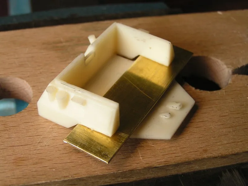
To secure the bottom plate and the fuel tank during the cooling down in the in required position they are "fixed" with a thin metal plate.
The end result of an afternoon works: The Fueltank is now entirely horizontally positioned relative to the frame and the base plate.This was it for this time! Building a kit yet always takes more time than expected.
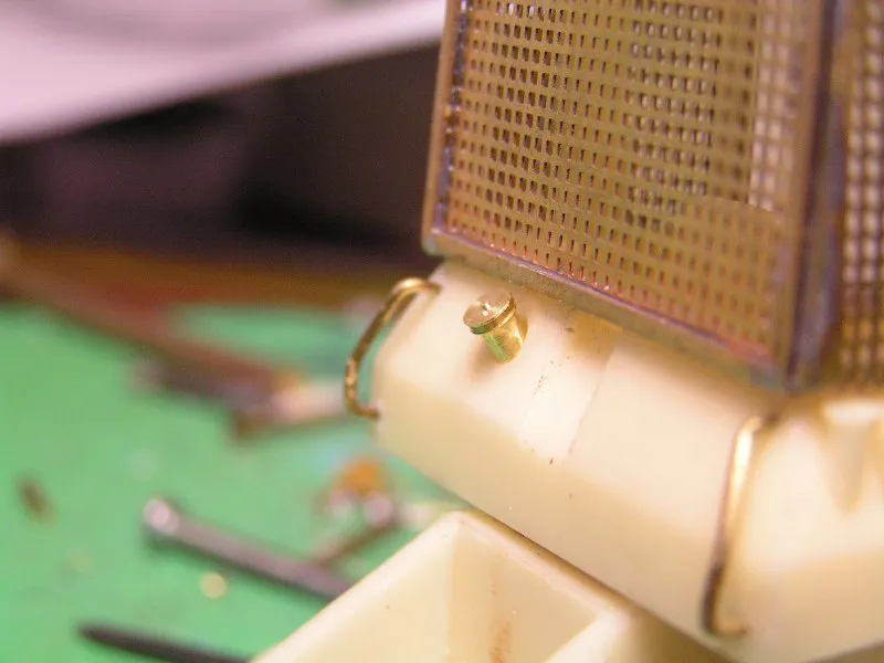
Extra details
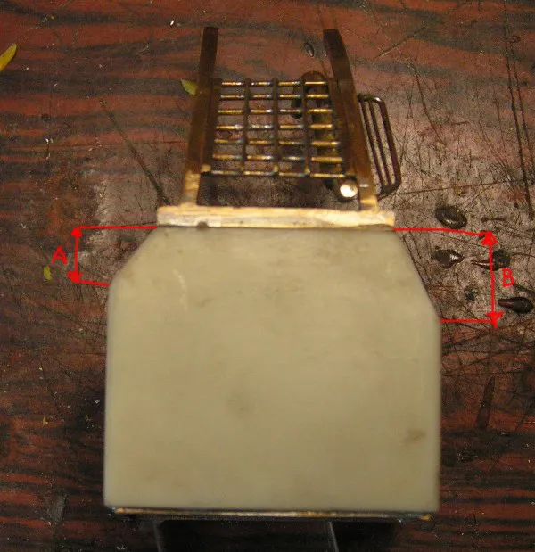
To built the scale model of the Caterpillar 527 Tracked Skidder as accurate as possible Ad Gevers has also paid attention to (extra) detailing.
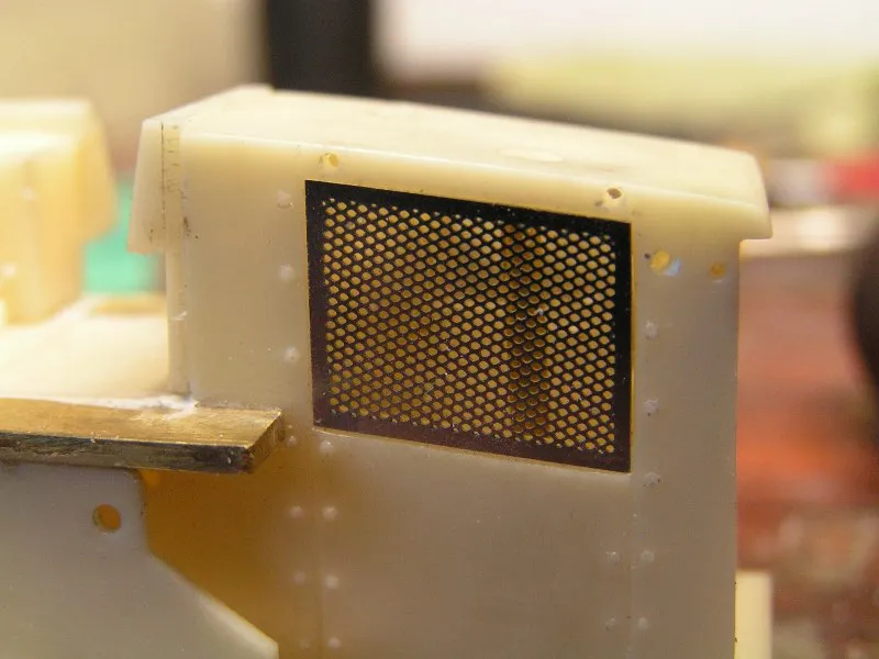
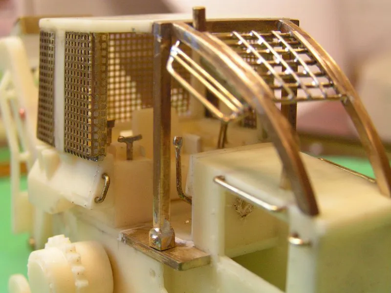
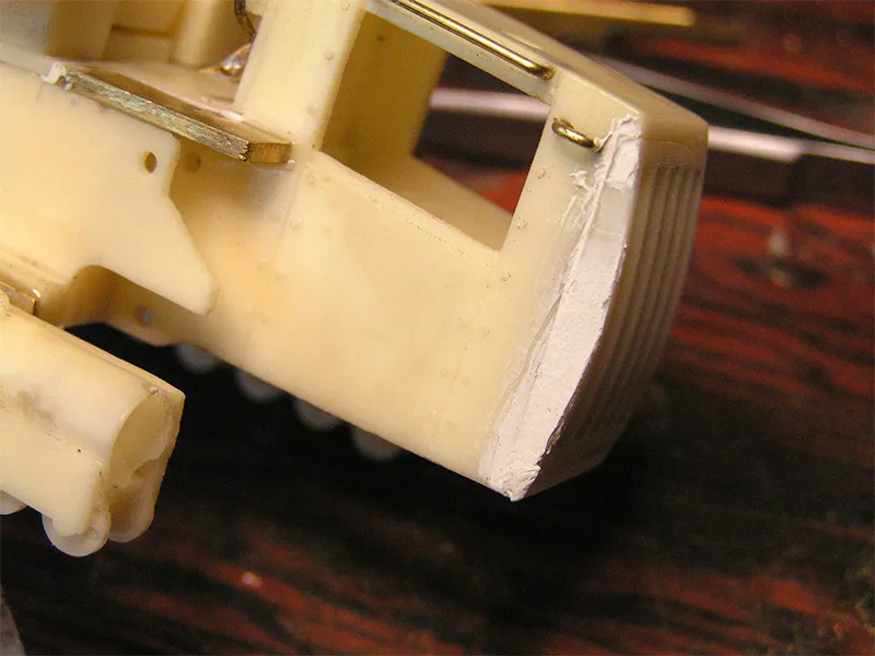
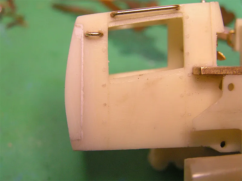
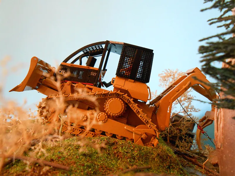
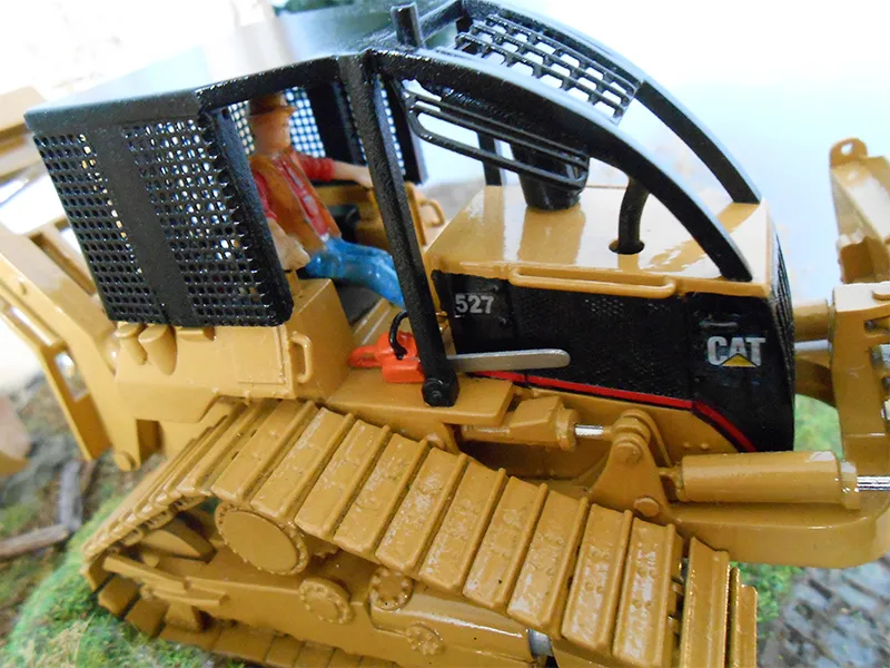
First he has the original roof line (A) extended (B) which according to him better matches the original roof line of the 1:1 Caterpillar 527 cab.
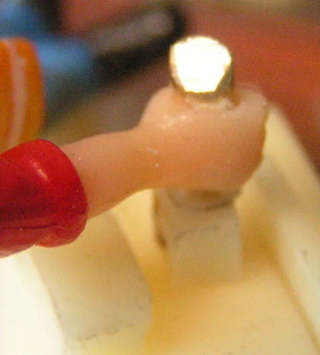
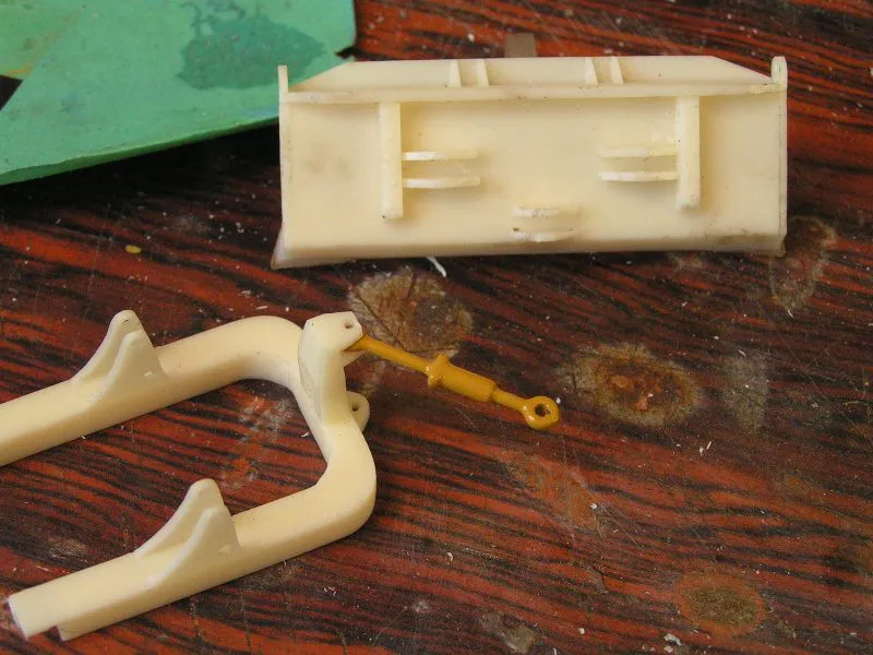
This is almost to crazy for words but Ad Gevers also made some custom Operating levers and knobs for his custom scale model.
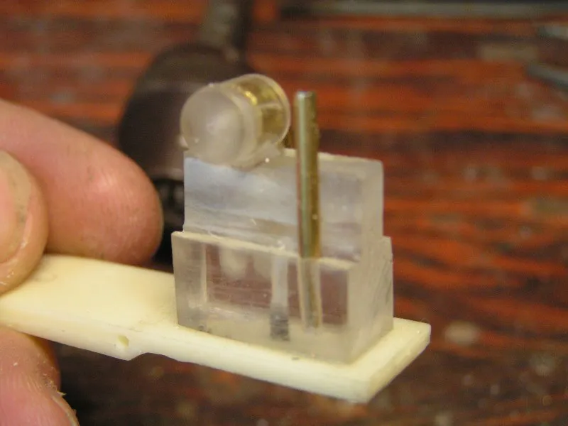
The fact that there is no engine supplied is in the original kit is natural for Ad Gevers not acceptable, despite the fact that his scratch built engine will soon be behind the engine hatches and little or nothing can be actual seen is no excuse. So he decided to made make ??the engine complete with air filter and exhaust. Hopefully if the model is at a later stage and is fully assembled and sprayed something from this little master piece is still to see.
The Fuel cap of the kit is done slightly on the small side. So removing it and then replaced it with a new self made fuel cap of brass.
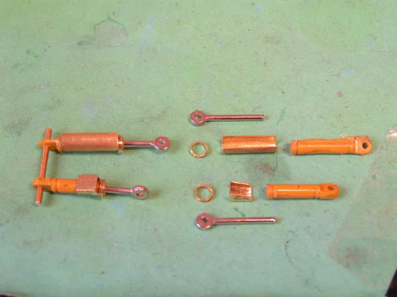
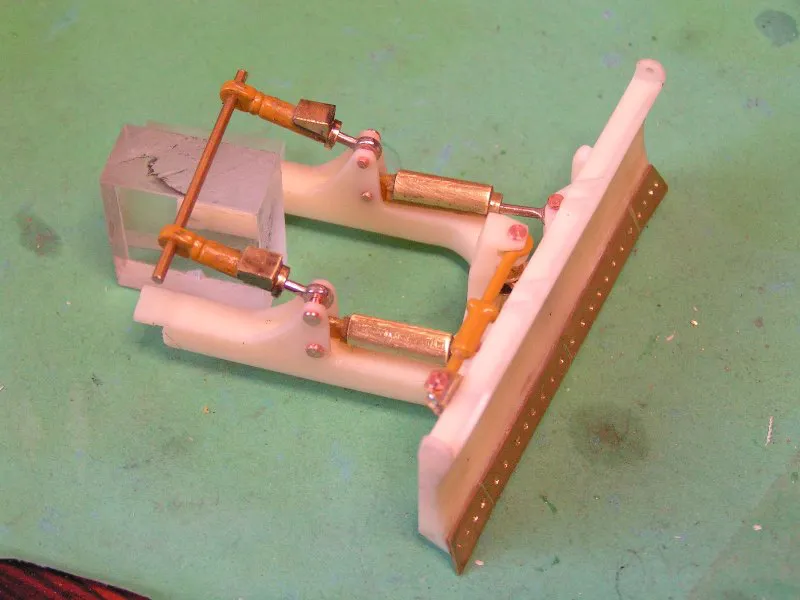
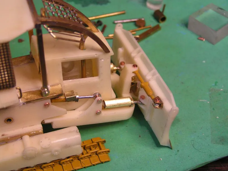
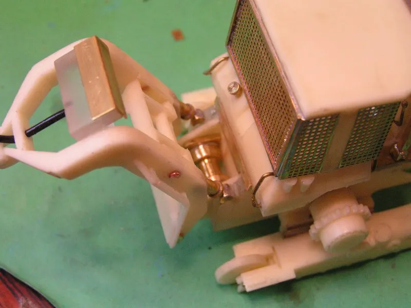
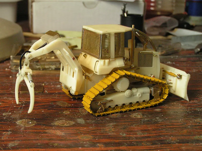
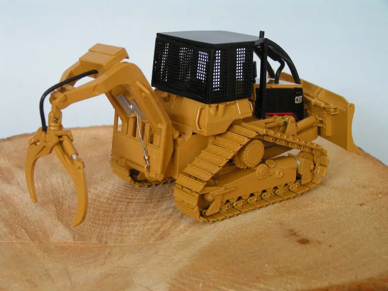
The Blade
The blade of the Caterpillar 527 is also adapted to some points and further improved to end up as accurate as possible.
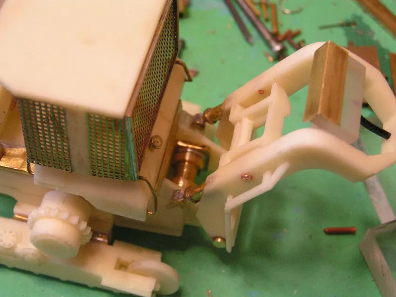
The upper bracket where the blade revolves is actually the point of attachment of an extra cylinder that runs toward the right side of the blade. To achieve this Ad uses some existing components of the "donor" Caterpillar D6K Track-Type Tractor from Norscot, which already provided us the metal tracks for our Caterpillar 527.
But there also must be added an additional suspension point for the attaching of the blade. Make use of the existing “fixed” points to get everything mounted in one straight line and you will be sure it will turnout properly.
The ledge at the top of the blade is removed and the right suspension point for the cylinder is made.
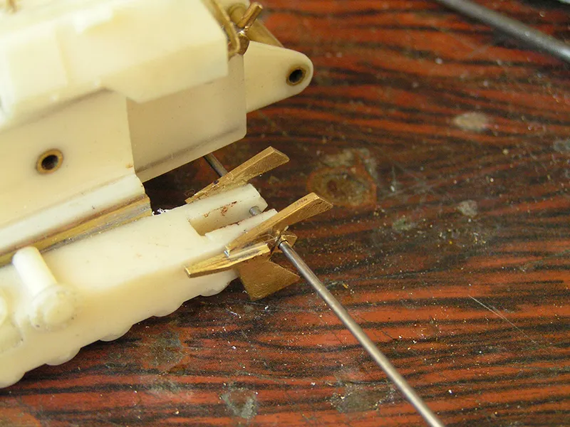
About the shape of the Cutting Edges and End Bits at the bottom of the blade Ad was not completely satisfied. Therefore he decided to make them completely new of brass material.
For the hydraulic cylinders of the blade Ad also uses the cylinders of the "donor" Caterpillar D6K Track-Type Tractor. Like the real machine he also adds an extra footboard and an extra protective hood fitted over the cylinders.
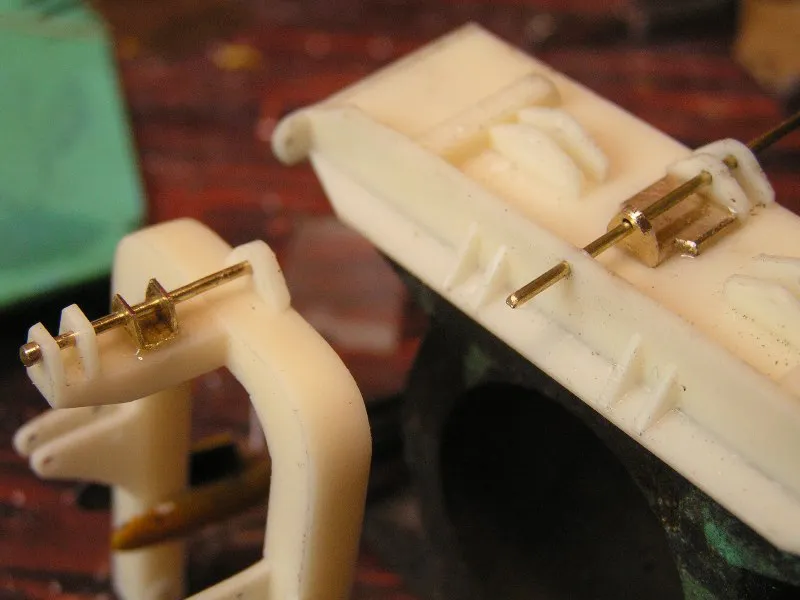
Then comes the moment of merging: After all the mounting pins (who occasionally get lost when they fall to the ground -)) are made to the correct length, it is now time to test all the assembled parts and make sure everything is moving well.
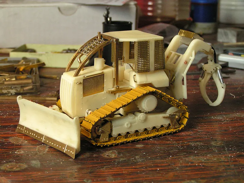
The Boom
At the boom, the holes were also not in a straight line, and therefore these are positioned by using a spacer sleeve which brought then at the same height.
In a 1:1 Caterpillar 527 Tracked Skidder the cylinders are mounted in the frame. To make the Boom (single-arch) from this scale model movable there is unfortunately too little space and so I decided to fix the construction with glue.
However, there should be, of course, some part of the cylinders be visible. To achieve this there are two holes drilled into the resin frame ------
---- In which the cylinders come to be seated.
The fixed points to the frame are constructed of plexiglass material. The lower attachment point of the boom now, just like the 1:1 Caterpillar 527 Tracked Skidder, has become a connecting tube.
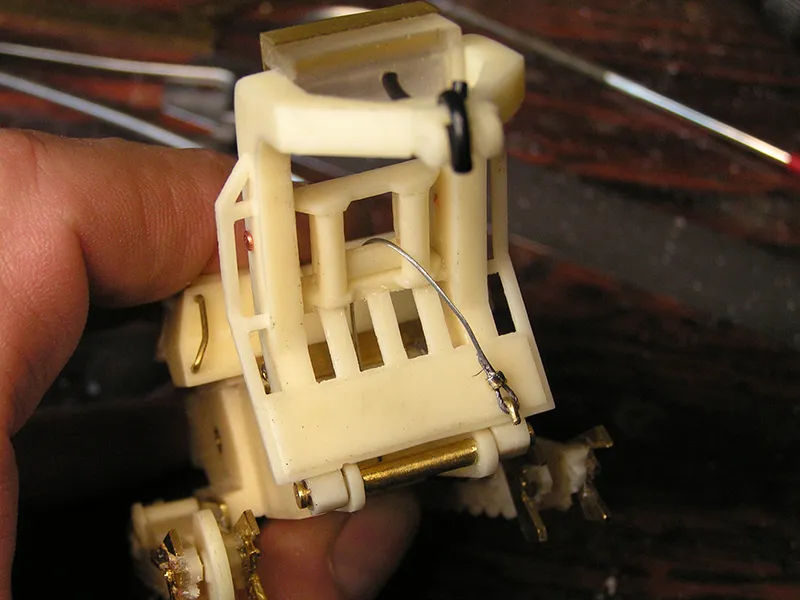
Added to this kit are the cable guide rolls (Fait Lead) in the boom, but the Winch itself is missing, therefore I added a (simple) scrath built winch to make a more realistic scale model.
I had to do some somewhat filing cut to the guide rolls to fetch the cable will go directly to the roller drum.
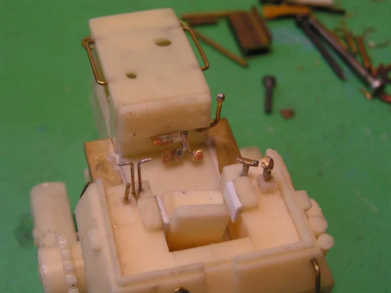
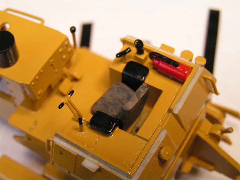
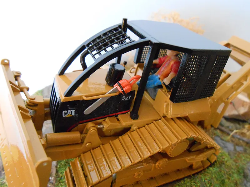
Without levers and pedals, this Caterpillar 527 Tracked Skidder of course can not operate, and therefore "the small stuff" is also applied to the scale model. The seat backrest is made ??slightly shorter and also slightly tilted. Ergonomics and occupational health at 1:50th scale!
The finishing Touch
In order to make it look as real as the winch cable, I use avery small steel cable. A disadvantage is that it is so small that it can not be folded into small curves, so I solder it to the beginning and end of each winding onto the drum of the Winch.
The steel cable I attach to the Boom and it goes through the Fairlead behind the backside of the Winch Drumo, so it just seems as if he is wound around on the Drum.
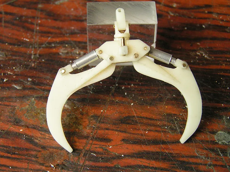
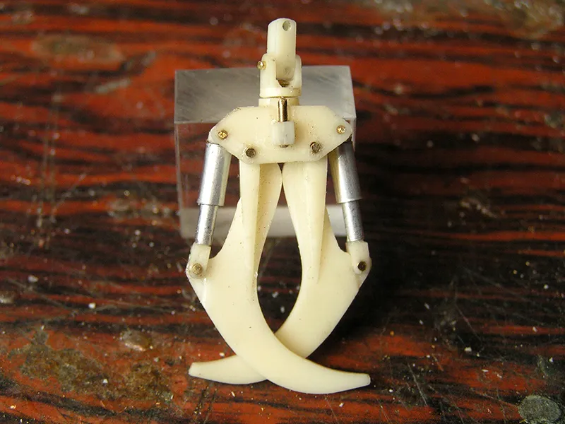
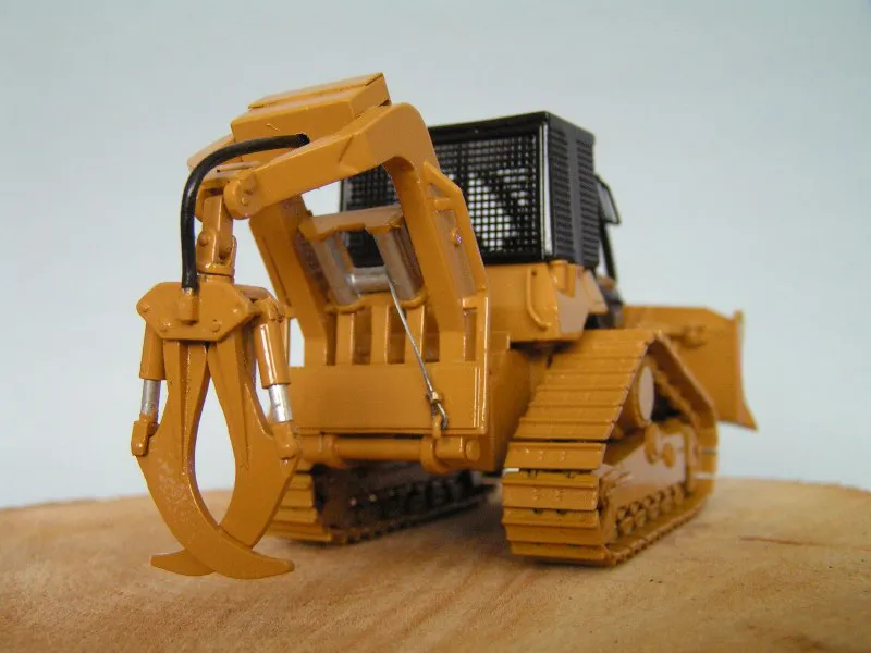
The Grapple is made fully rotatable and movable??. The whole Grapple construction is very fragile and very breakable performed by the many small and thin resin parts.
As promised, still had to be made the guided back plates. These are hand-tailored made and entirely of brass material. Following step: correctly aligned the front on a straight line.
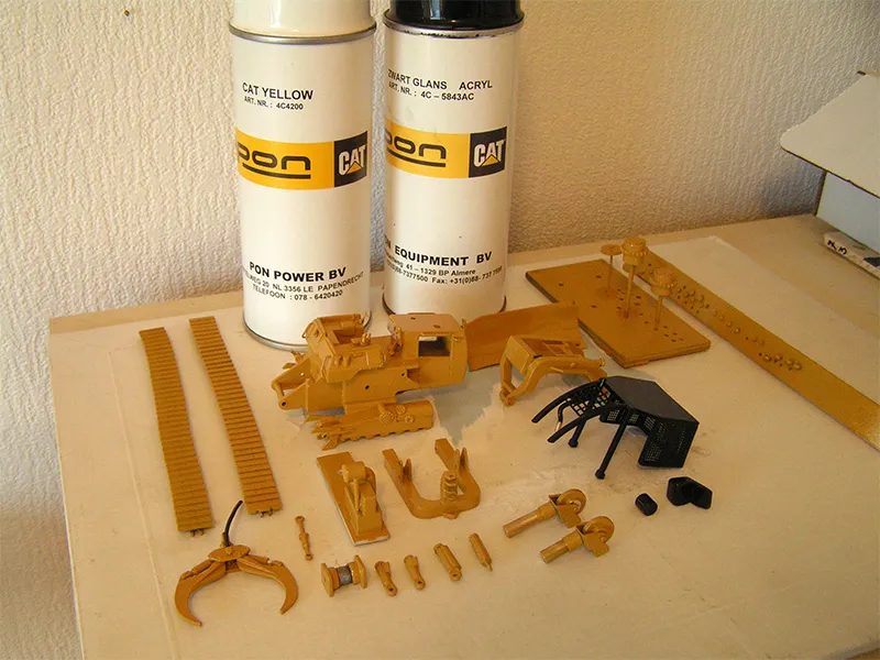
I'm not going to add more changes and modifications and so is the Caterpillar 527 Tracked Skidder now ready for the last step: Finall Assembly and to be sprayed and in the Caterpillar colors.
The Finall Step!
After all the modifications to the kit now the time has arrived to get rid of all the little bumps, tiny holes and ugly corners with some filler so that there will be a tight end result after spraying the built up scale model.
Fortunately, the ability to spray at my work under ideal conditions all components in the primer and lacquer. (at home in the shed at minus 8 degrees it will definitely not work!)
Suddenly I discovered that the fire extinguisher was missing, so it had to be added and placed on the model. Safety first!
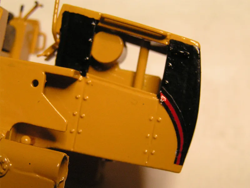
From the set decals that comes with the kit Ad Gevers only uses the curved red stripe on the motor unit, because it is not easy to reproduce. All other markings and type designations are homemade.
Now everything is finished start it is necessary to wait patiently until the paint has hardened and the Caterpillar 527 Tracked Skidder can be finally assembled. Do take plenty of time for this phase!!
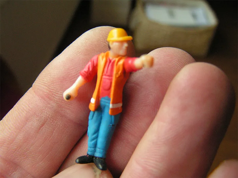
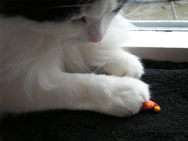
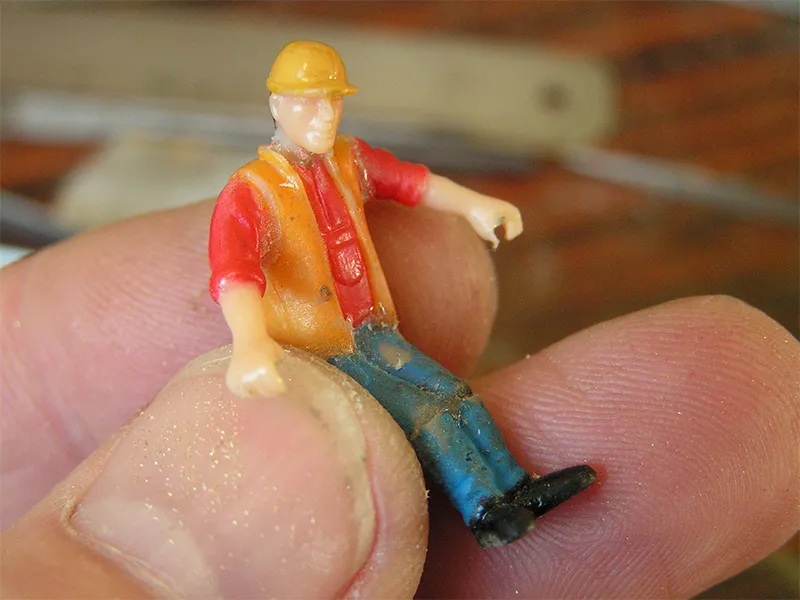
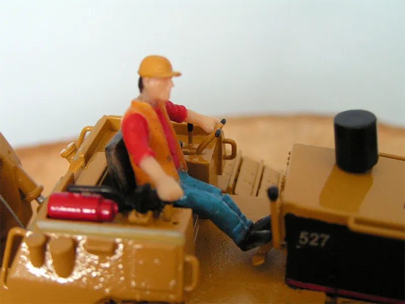
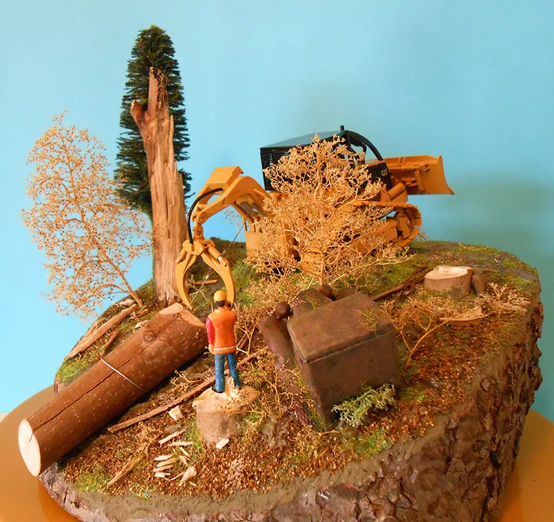
The Caterpillar 527 Tracked Skidder without operator in the cab is of course not an option. Fortunately Ad Gevers found in his "junk bin" a figure of soft plastic in the correct size. In the first picture you can see the original figure. But after the attack of the house CAT, he had to see a doctor!!
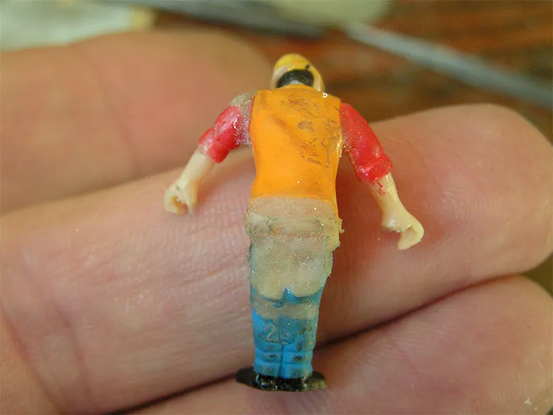
It took only a minor operation of "Doctor" Gevers to make a seated driver of this standing man: First were the knees and hips are broken, two arms out of the bowl and finally twist his neck.
But no problem: after he came out of the anesthetic our driver was fully recovered and he could back to work!
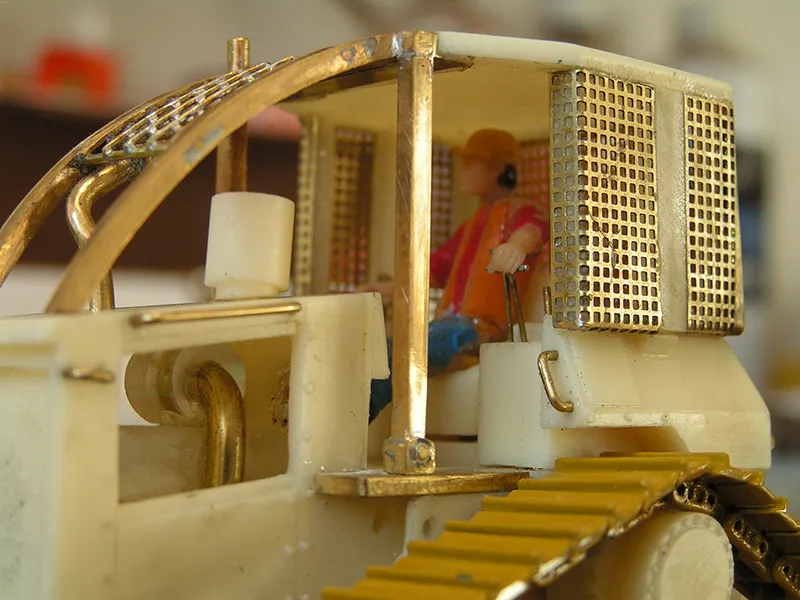
Done!
Now the model is "Ready for work" and it can be added to the collection in the display cabinet.
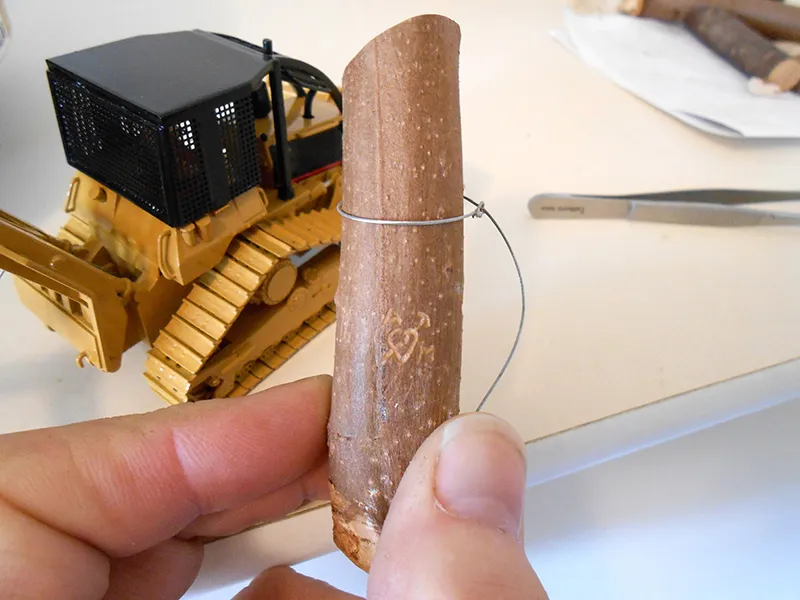
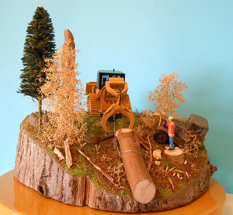
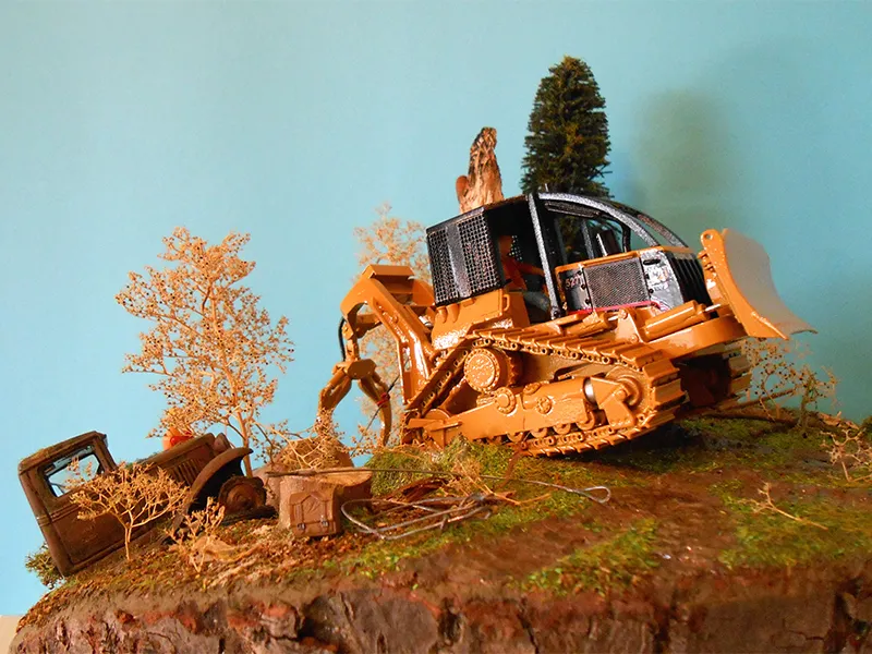
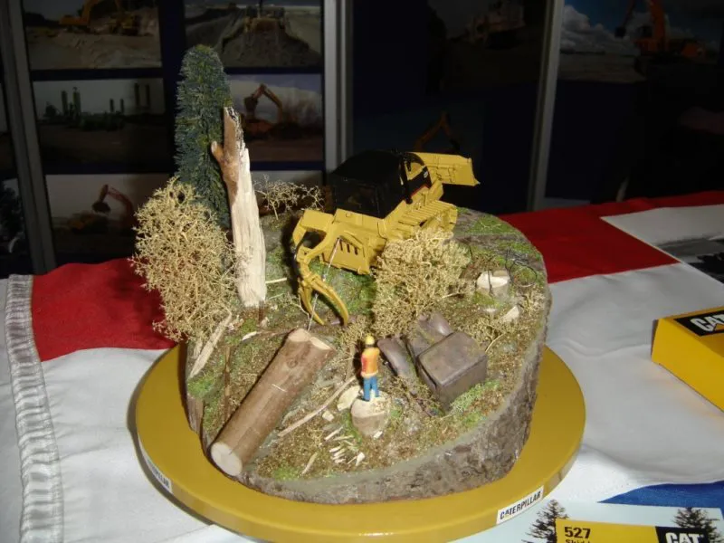
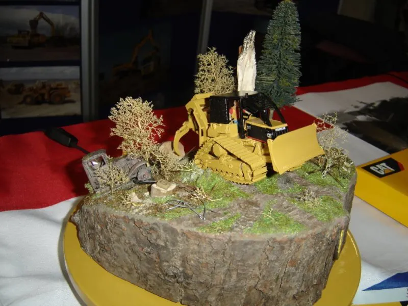
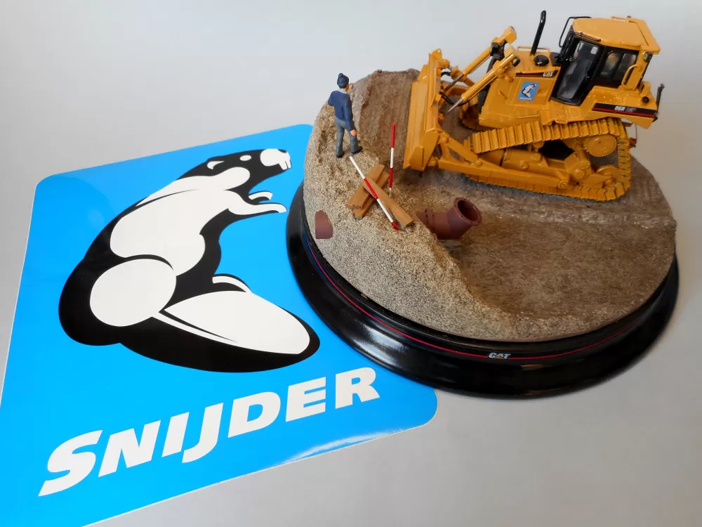
Diorama Modelshow Europa 2013
Saturday, March 16, 2013 the 22st Modelshow Europe was held in the flowerauction "Plantion" nearby the city Ede in the Netherlands.
On this special exhibition one can see all kinds of miniatures and model construction projects in the field of earthmoving, cranes and heavy transport. This exhibition is unique by its grand design and the only one in Europe.
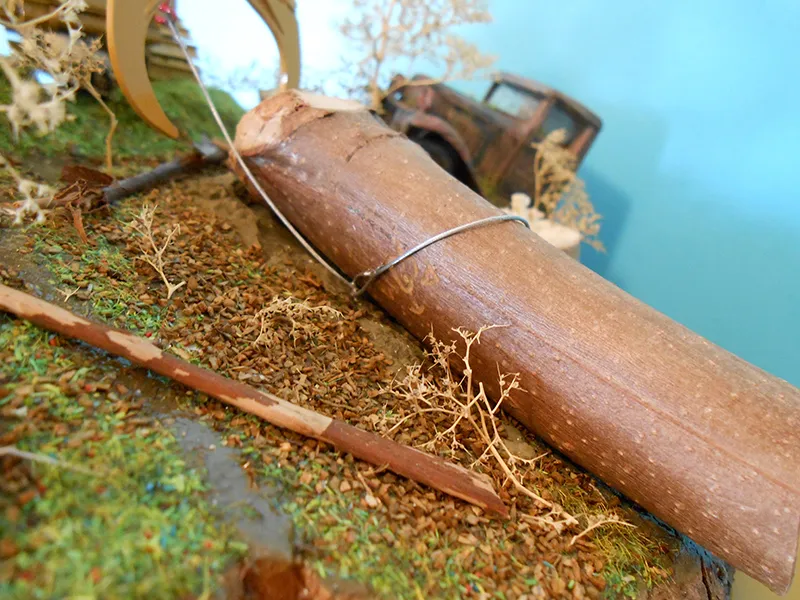
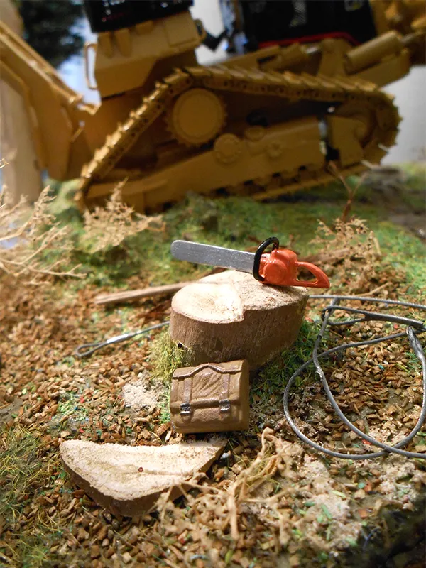
Ad Gevers built especially for this Modelshow a diorama full with tiny details where his Caterpillar 527 Tracked Skidder comes alive!
Timber!